Building a Reliable DIY ESP Breakout Board (Part 1)
Introduction
I’ve been experimenting with a couple different iterations for a breakout/carrier board for my ESP WLED set up. I got the idea after I started to try to permanitize some of my smaller LED projects, and became tired of the jank. After watching youtube video after video of these slick and clean DIY LED set ups I decided I could do the same. So I got to work, I bought some perf board, a header pin kit, and some wire.
I made several versions/iterations based on my use cases for them. Some for testing LED strips, some have logic level shifters added to them for larger projects, some have multiple output channels.
I plan to eventually create an AIO ESP board that does it all and has multiple channels, LED feedback, maybe even weatherproof for outdoor use? Seriously, as I type this out more and more ideas come to me, the possiblities are endless.
Materials Needed
If you would like to follow along here is a list of materials I used:
- Perfboard
- Soldering Iron
- Solder
- Wires (color coded if possible)
- Flux
- Helping Hands (optional, but recommended)
- Heatgun or lighter
- Shrink tubing
- Header pin kit
- M/F Barrel Jacks
- External Power supply
- Wire Cutters
- Wire Strippers
- Tweezers (optional but recommend)
- Stand offs (optional but recommend)
- Male/Female JST connectors
Designing and Building
The Foundation
I kinda went into this with my ass first, I didn’t have an actual plan or layout of what I wanted to do, I really let the necessity guide me. I knew I wanted to make it compact, easy to hide, and simple.
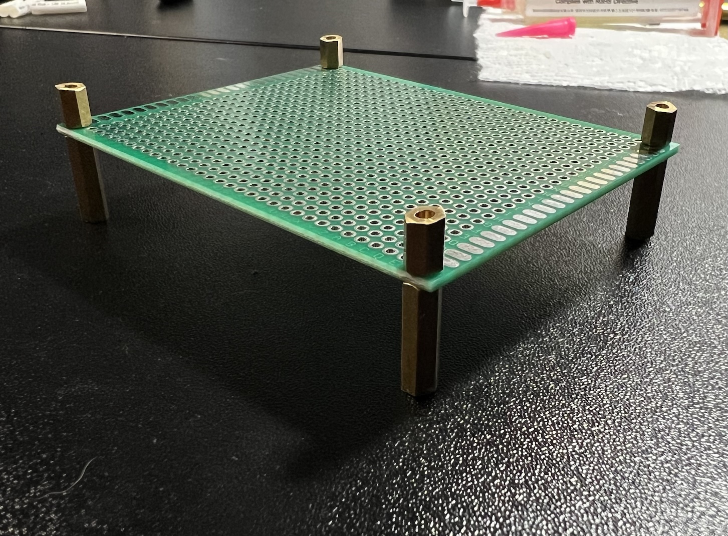
I had some left over stand offs from an old Raspberry Pi cluster case that screwed in perfectly into the perfboard, offering some distance from the ground to protect the bottom pins from damage or shorting out.
Question, where did tiny jesus have his final meal?
tiny holy table
Figuring out the rest of the layout
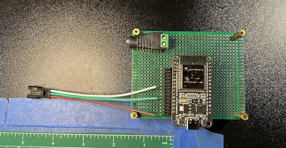
I wanted only 2 plugs to come out of this breakout board, one for the LED strips and one for power. I went with a barrel jack for power, but I will probably find a smaller plug in the future, for now this works perfect, easy to cut and splice to a power source, and easy to plug/unplug.
Adding the header pins
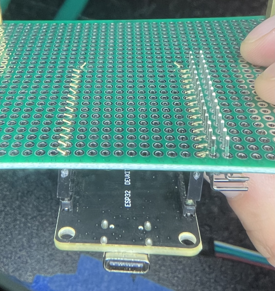
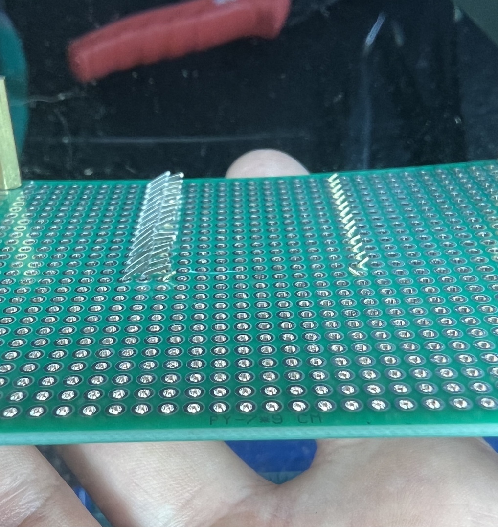
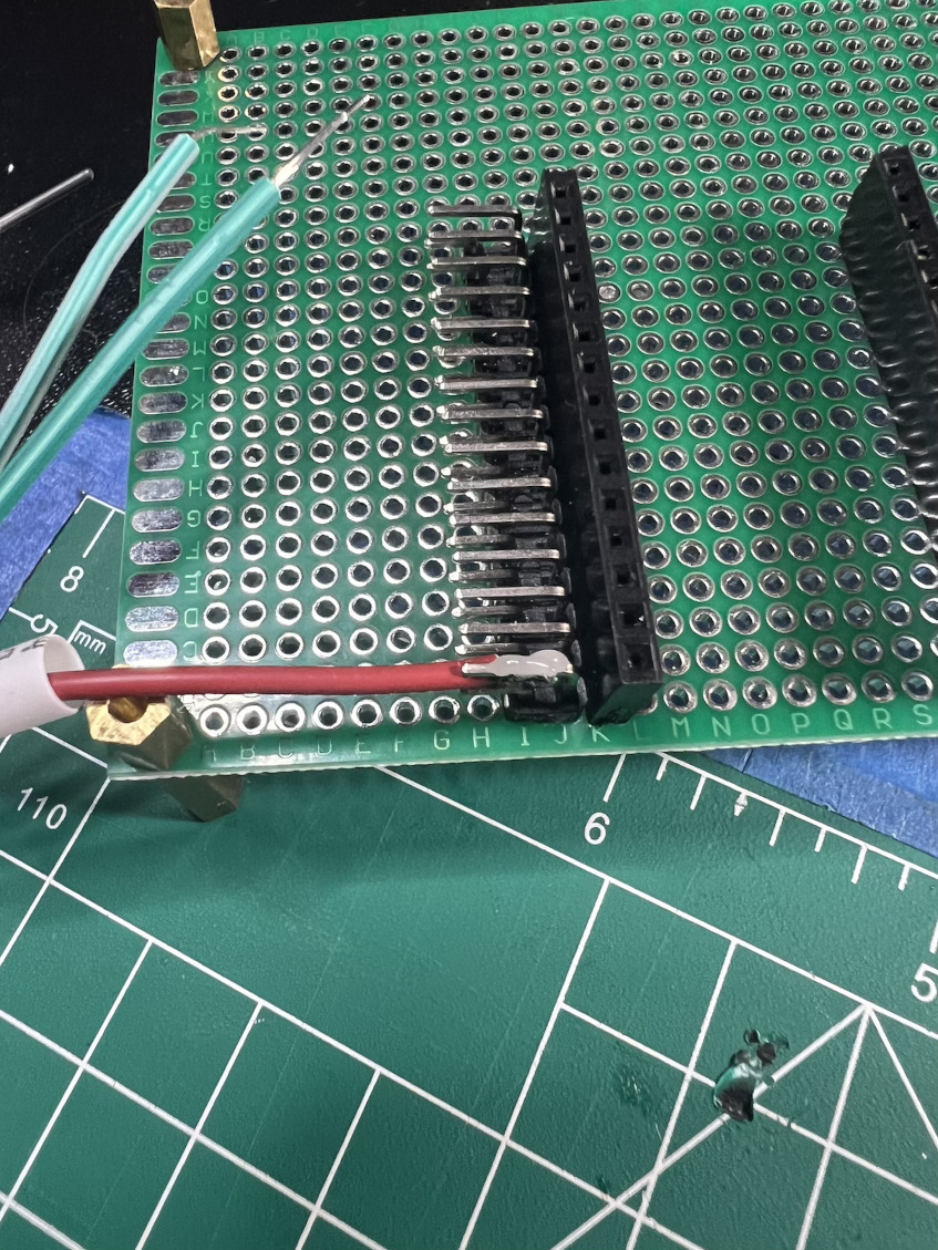
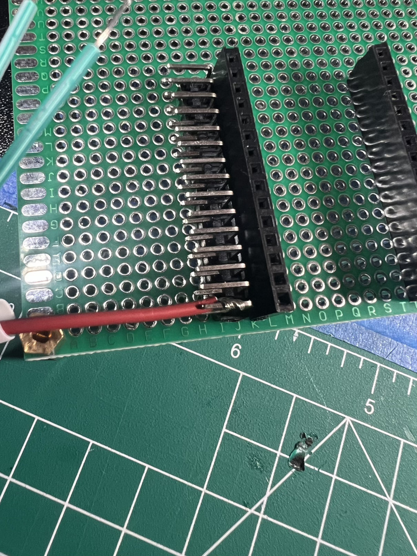
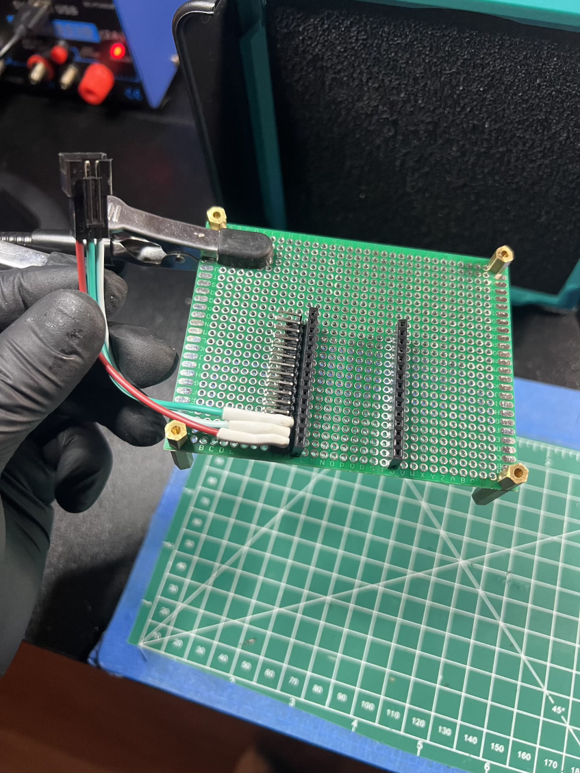
I started by plugging female headers into the ESP, and putting that on the board then flipping it over and bending the pins out to hold them in place.
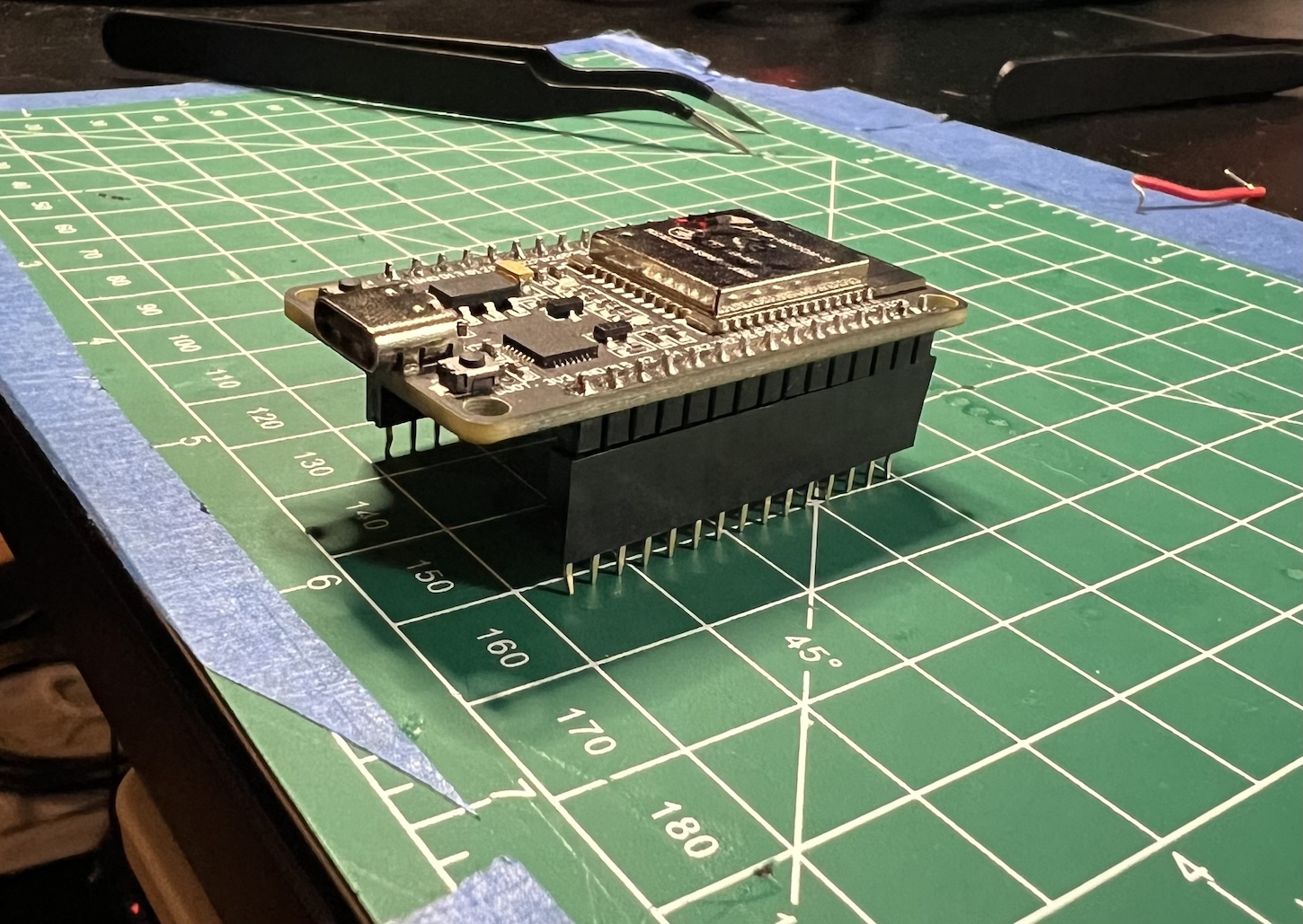
In my first iteration, I used the vertical male header pins but soon found out this puts a lot of unneccessary stress on the wire and pin, which could lead to issues in the future, so instead this time I opted to use the 90 degress double male header pins. The reason I went with the double is the top layer is where I will solder the JST connector, and if I ever need to troubleshoot or debug in the future I want to be able to still access those pins on the board without unplugging the ESP.
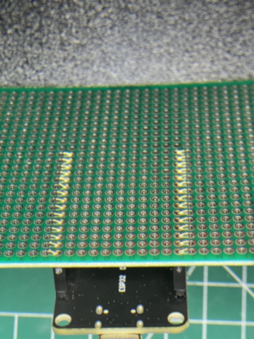
Next some flux and solder to anchor them down.
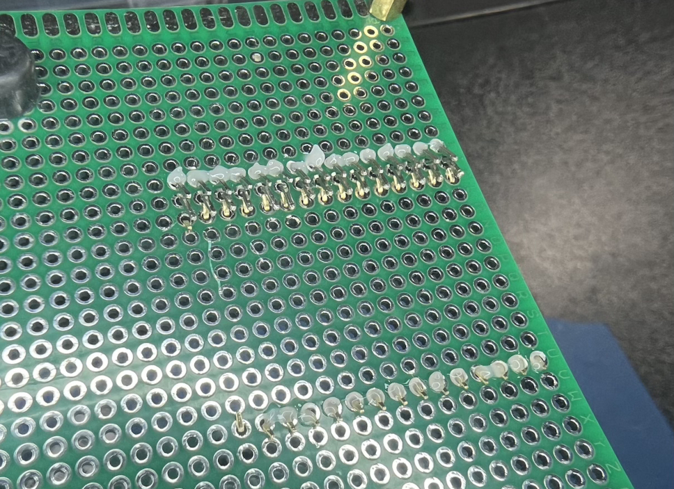
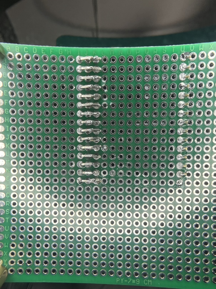
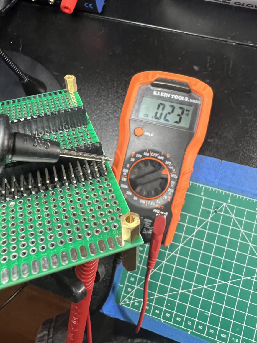
Then I performed a continuity test to make sure all my points had solid contact. We got beeps!
Adding the JST Connector
I then took a female JST connector and stripped the wires about a half inch back. To make it easier to wrap around the header pin I first bent the wire into the shape of a question mark.
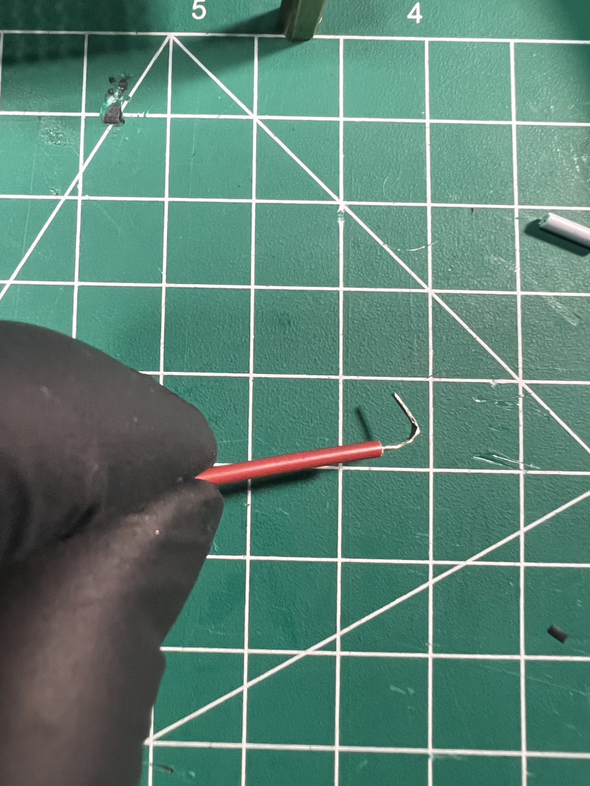
Cut a piece of shrink tubing and slid it back on the wire, then carefully wrapped the wire around the pin using tweezers and patience, gave it a little flux hat.
Bit of solder.
Adding power
Our board still needs power, next I add the barrel jack, little bit of hot glue to hold in place.
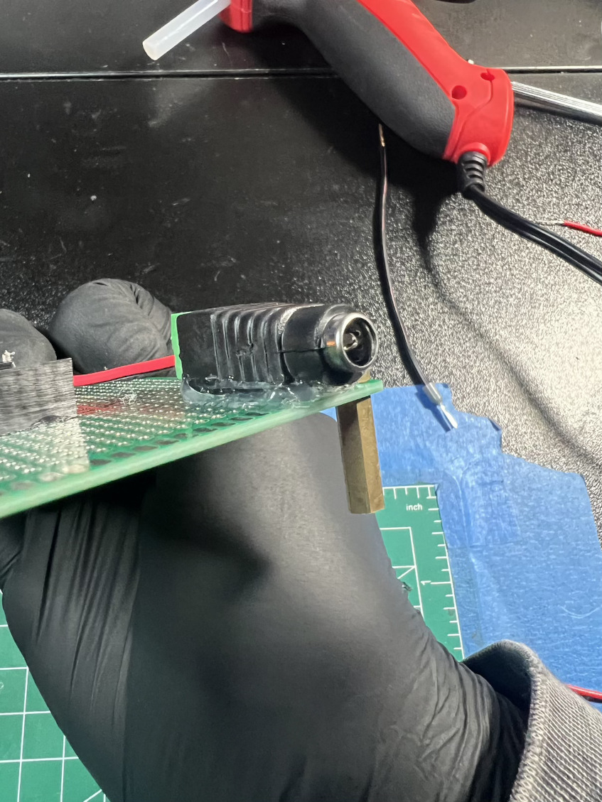
To run the power from the barrel jack to the rest of the board I cut and stripped some 18 AWG power wire, just to be safe for higher currents. I tightly twisted the wires and fed them through the perfboard holes. On the other ends I crimped on some wire ferrules to keep the wires from fraying.
The 5v line is ran directly to the header pins. For the ground I am trying something a little different with this one, I’m not quite sure it will even work but I am using a star ground configuration.
This means I have one central point that is the common ground and all other components connect to that one point, when you have multiple lines running to this common point it begins to resemble a star patter. This is supposed to help reduse and isolate noise from the power and data signals, it resembles something like this.

For the power supply I had an old 5V 1A laying around. I cut and strip the wires, tested polarity, then spliced a barrel jack on to the end, added a little shink tubing and bam, new power supply.
And that’s it! Lets plug it in and test.
Final Product
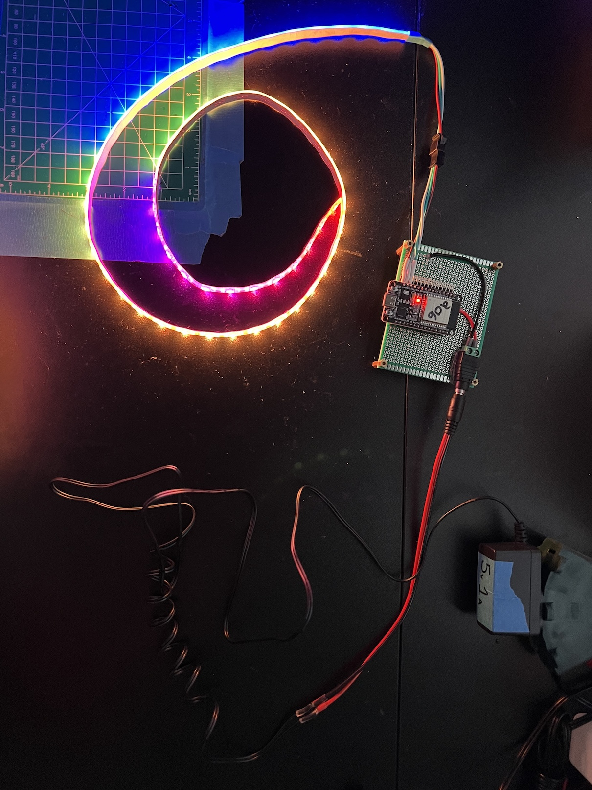
Neat!
A Quick Explanation
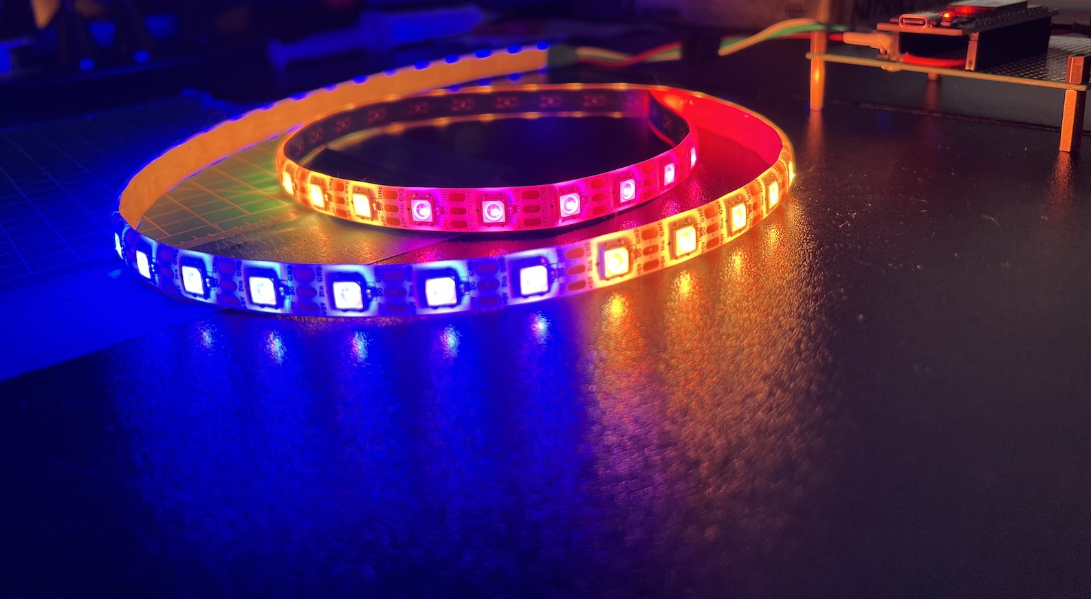
Here it is, at its most basic level, an ESP breakout board. You now can easily plug your LED and power into it, swap strips without having to desolder, just unclip and remove. There is still a lot of work to be done here, but this is should be perfect for most small projects.
You can still access each pin on the ESP if you have female dupont wires, don’t need a USB cable to power the ESP and another for the lights. They share the same power source so you can increase your maximum brightness without worrying about burning out your ESP.
I also plan to buy a 3D printer in the coming months and I am going to start experimenting with creating cases for these as well.
Caution: This design has no safety nets, and could be prone to shorting out or other adverse effects if you are careless with your soldering. Double check your solder points for bridging, use a multimeter to check continuity between your points before powering it on.
My later revisions I will be experimenting with adding power stability, signal smoothing, reverse polarity protection, and optimizing the layout further. Thanks for reading and be sure to check out the rest my DIY series!
-T