Building a Reliable DIY ESP Breakout Board (Part 2)
Welcome back to my DIY series. It’s been a while since I last updated this project — life has a way of pulling you in every direction. Since then, I’ve picked up a much deeper understanding of ESP microcontrollers, electrical fundamentals, and WLED itself. I’m ready to share some of that knowledge with you as I refine my original perfboard build.
This post isn’t a step-by-step wiring tutorial (that’s coming next). Instead, it’s a high-level overview of the core components I added to make my WLED breakout board more reliable. I’ll explain what each component does, why it’s needed, and how it improves the build.
Logic Level Shifter (LLS)
What Is a Logic Level Shifter?
If you’ve ever hooked up an ESP32 to a 5V LED strip, you may have run into issues: flickering LEDs, incorrect colors, or glitchy effects. The culprit is usually the data signal voltage.
The ESP32 outputs a 3.3V logic signal, but WS2812B (and most 5V LED strips) expect a 5V signal to match their 5V power rail. Without proper conversion, your data line can fall below the threshold for clean signaling — especially over long runs or when driving lots of LEDs.
A logic level shifter boosts that 3.3V signal to a steady 5V, ensuring consistent, error-free communication. It’s one of the first upgrades I recommend for any WLED build.
Types of Level Shifters
Not all level shifters work equally well for LEDs. Here are the most common options:
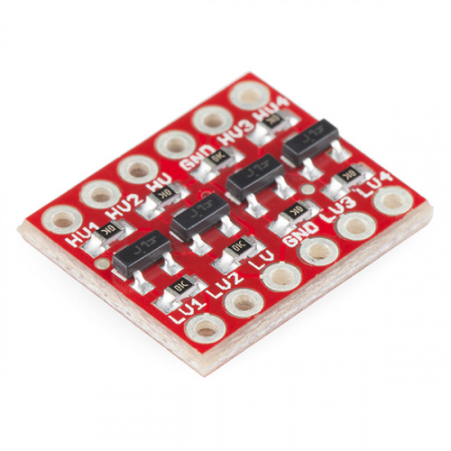
Simple MOSFET-Based Bidirectional Shifters
-
Cheap, easy to use, widely available.
-
Can shift both up (3.3V → 5V) and down (5V → 3.3V).
-
Fine for short LED runs, but can struggle with fast timing-sensitive signals like WS2812B.
Bidirectional Shifter
-
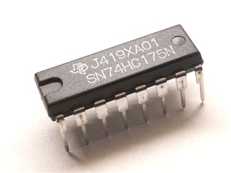
Dedicated Buffer ICs (e.g., SN74AHCT125)
-
My preferred choice. These are fast, reliable, and handle WS2812B timing properly.
-
They require slightly more wiring and a reference sheet for pinouts, but they’re worth it for larger installs.
Dedicated Buffer IC
-
-
Driver Boards
- Some pre-built WLED dev boards include onboard buffers, but for a DIY perfboard project, the SN74AHCT125 strikes the best balance of performance and simplicity.
Once the data signal is boosted to 5V, we’re off to a good start. But voltage stability and signal integrity can still cause issues if left unchecked.
Signal Smoothing: Avoiding Glitches
Even with a solid data signal, voltage fluctuations or noisy lines can wreak havoc on your LEDs. To stabilize things, I add:
-
A 1000µF bulk capacitor across the 5V and GND rails powering the ESP32 and LED strip. This helps absorb sudden current spikes when many LEDs turn on at once.
-
A 330–470Ω resistor in series with the LED strip’s data line (between the ESP32/level shifter and the first LED). This dampens ringing and helps prevent corrupted data.
Power Protection (Optional but Recommended)
When you’re powering long LED strips or high-density setups, you’re pushing serious current. A few simple protections can prevent frying your controller (or yourself):
-
Schottky Diode on Power Input
- Prevents disaster if you accidentally reverse the polarity on your power supply.
-
Voltage Regulator (if needed)
- Keeps the ESP32’s 3.3V rail clean if your 5V power source is noisy or unstable.
-
Inline Fuse
- Stops catastrophic failures in case of a short or current surge.
These parts are inexpensive, easy to add, and can save your components in the long run.
Boot Reliability
Sometimes the ESP32 can fail to boot or enter odd states when powering up alongside your LEDs. This often happens due to floating GPIO pins — pins left in an undefined state (neither high nor low) at startup.
To fix this:
-
Add a 10kΩ pull-up resistor on the EN pin, tying it to 3.3V. This ensures the ESP32 consistently boots.
-
For any other GPIOs that might float, consider adding pull-down or pull-up resistors as needed.
Wrapping Up
This v1.0 breakout board takes the chaotic breadboard prototype I started with and turns it into a neat, stable build. With the addition of a logic level shifter, bulk capacitors, Schottky diodes, and fuses, I can now run 12V LED setups with confidence — no random flickers, boot issues, or magic smoke.
In my next post, I’ll break down how to wire each of these components step by step, with photos and before/after examples, so you can build your own version and see the difference these upgrades make.
Thanks for reading,
– Trev